| Home | Material | My Telescopes | Mirror Making | Deep Sky | ext. Links |
| 32" Mirror | 24" Kyklopas | 17,5" Aristarchos | 14" Mirror | 10" Archimedes | 10" Travel Dobson | 24 cm Quints | 17 cm Twins | 6" Traveldobson |
| Deutsch (de)![]()
| Home | Material | My Telescopes | Mirror Making | Deep Sky | ext. Links |
| 32" Mirror | 24" Kyklopas | 17,5" Aristarchos | 14" Mirror | 10" Archimedes | 10" Travel Dobson | 24 cm Quints | 17 cm Twins | 6" Traveldobson |
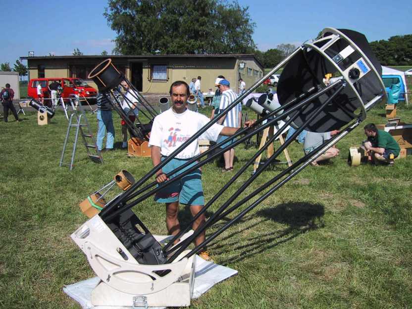
Kyklopas 24" f/4.1
The mechanical components
 More images from the telescope meeting ITV 2001 Setup pictures at ITV 2007 Pictures from ITT 2020 |
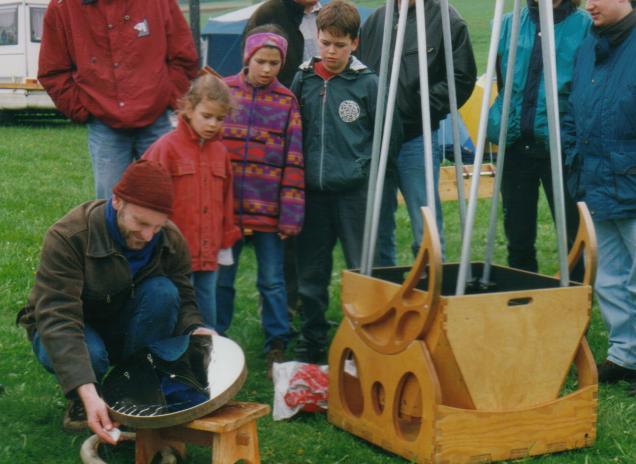
First Light was at the Telescope
Meeting Vogelsberg (ITV)
at 22. May 2001
|
 |
|
 click on the images to expand them to higher resolution
|
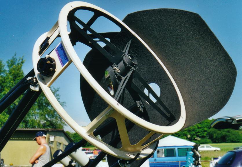
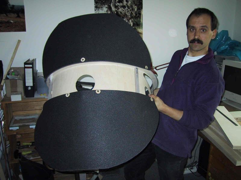
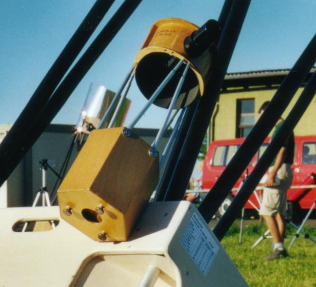
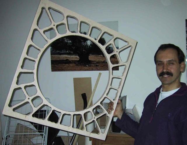
Secondary cage: 655 mm (25.8") inner diameter, 200 mm (7.9") height. If you can safe weight here at the long lever arm, you won half the game already, since you trigger a chain reaction of additional benefits. After many discussions (mostly with myself) about racing bicycle rims, carbon fiber structures and single ring sandwich construction, I finally decided to go again with the two ring design like already approved on my 17.5" Aristarchos. The Baltic Birch plywood rings are 30 mm (1.2") wide and 15 mm (0.6") thick and are glued together with a 2 mm (0.08") airplane plywood sheet instead of Kydex. This thin plywood adds significant stiffness to the whole structure! Cut outs were made, where no material is needed for baffling, to reduce weight and wind resistance area. The focuser is a "helical Crayford" from KineOptics, that is simple, stable, allows fine focusing and weights 180 grams (6.4 ounces) only. The complete cage without eyepiece weighs 4.0 kg (8.8 pounds). |
|
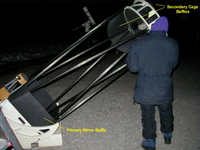
Baffles: At the secondary cage baffles from 6 mm (0.24") insulation foam material are fixed to the cage rings with press buttons. The wind resistance area is reduced to a minimum. |
|
Another 28 cm (11") wide baffle from the same material is velcroed around the trusses directly above the primary mirror box. This blocks stray light from the ground and prevents from dew formation on the primary. For additional baffling a ring baffle with 45 mm (1.77") inner diameter is be inserted into the focuser barrel. The ring baffle is made of an old photo filter ring. The dimensioning of all baffles was done according to Andy's Excel sheet. No light shroud is used!!! Looking through the eyepiece holder I see no sky and no ground, but just the secondary mirror and the reflection of the primary.
|
|
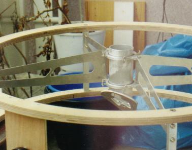
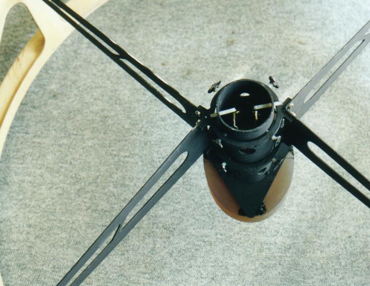
Spider: Two thin aluminum rings that accept the secondary holder are hung on 1.5 mm (0.06") aluminum vanes, that's all. This 300 g (10.6 oz) thing shall prevent a 4" diagonal from twisting and vibrating? Inspired by Jean Texereau, Mel Bartels, Steve Swayze and Gary Wolanski I stretched the idea of the eccentric design even more and placed the spider vanes 52 mm (2") offset to each other. At this geometry the spider vanes are mostly loaded in tension when you try to rotate the holder. No banana shaped Jupiters in gusty wind to worry about! Look at a rear wheel of a racing bicycle, to understand the principle: The spikes aren't oriented radial, but x-cross each other in order to handle the angular momentum from the chain and sprocket. As a result you need to apply a moderate tension only and the cage rings can be made narrower. As long as the spiders stay in parallel to each other, you see at the eyepiece the normal 4 spikes diffraction pattern. The connection to the cage is made via 15 x 15 x 2 mm thickness (0.6" x 0.6" x 0.08") rectangular hollow bars. |
|
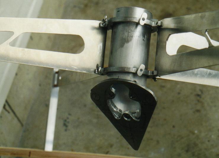
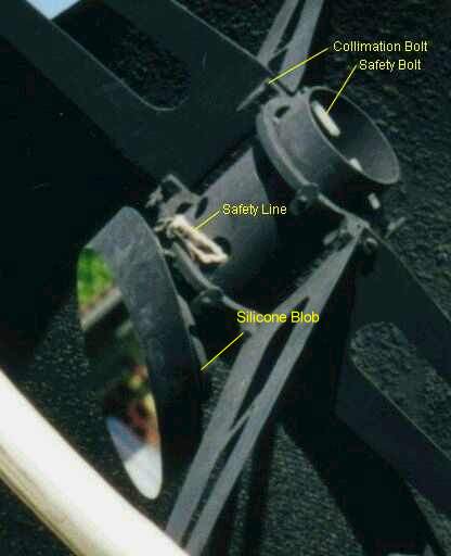
Secondary holder: A 55 x 2 mm (2.2" x 0.08") aluminum tube with a build in 6 mm offset instead of the usual central bolt. That's compact and extremely stiff due to the large cross sections and weights 180 g (6.4 oz) only. The 4" diagonal is silicone glued with 3 blobs of 2 mm (1/10") thickness directly onto to the diagonal al-sheet. In addition to this I glued a safety line with a small epoxi blob onto the backside of the mirror and bound it around the structure. After 20 years of operation the silicon still holds. The holder tube can be collimated with 4 pcs. M4 (0.16") polyamide bolts at each spider ring. It works wonderful. 2 polyamide safety bolts prevent the holder from falling out by mistake, when all adjustment bolts are loosened. The secondary is additionally secured by a "safety line", which is glued with one drop of epoxy onto the secondary (which proved to be superfluous, the silicone holds very safely).
|
|
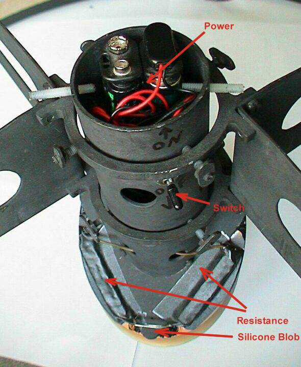
Secondary heater: Due to the exposed secondary I added a 0.9 Watt resistance heating, to prevent dew. It is made of 2 pcs. 10 Ohm power resistances with rectangular cross section glued at the backside of the secondary at one point only, to allow for thermal expansion without stressing the mirror. They are insulated against the ambient (the heat shall go into the glass as much as possible). The power supply is made via 2x4 AA Batteries put into al-tube. This is weight at the wrong place, but prevents from wires down to the mirror box. |
|
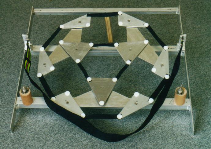
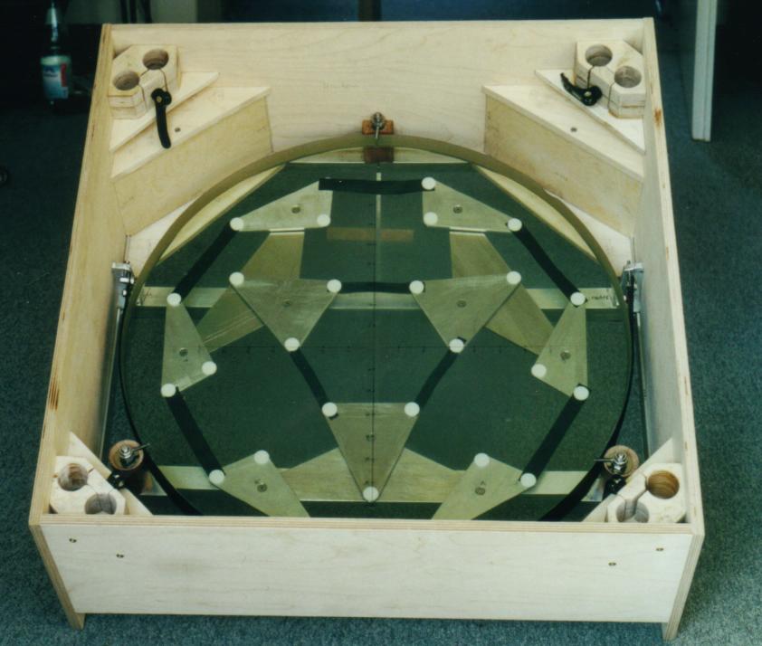
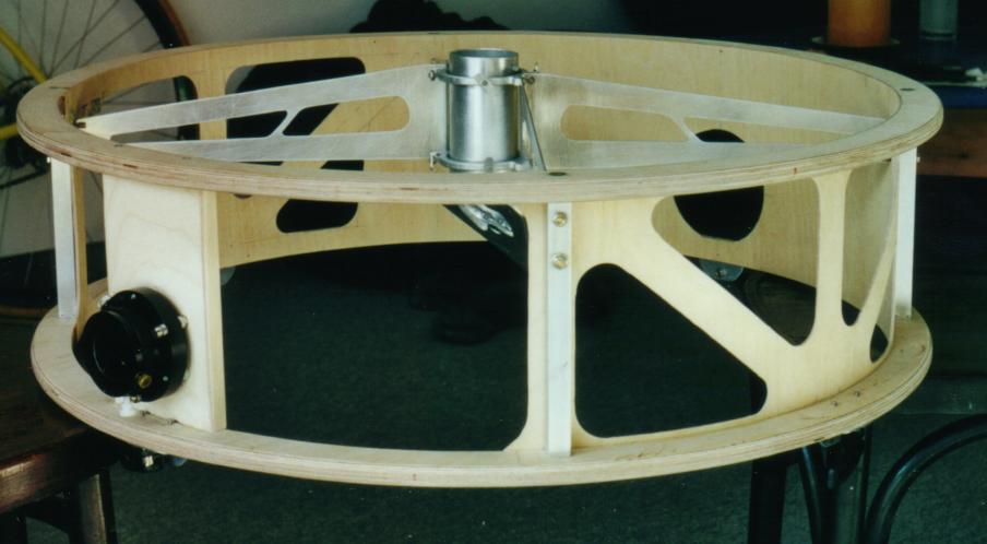
Primary Mirror Cell:
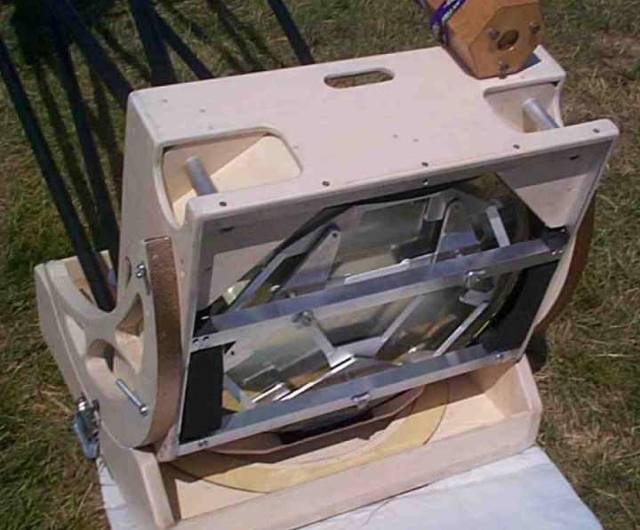
It's a classical 27- point flotation cell with a sling like described in David Kriege's book, but completely made of aluminum. The 30 x 30 x 3 mm thick (1.2" x 1.2" x 0.1") rungs are welded to 35 x 4 mm (1.4" x 0.16") side rails (the latter I should have done a bit thicker, let's say 6 mm (0.24")). The triangles at 4 mm (0.16") and the connecting triangles at 6 mm (0.24") are really thin as well. The whole thing weights 4.3 kg (9.5 pounds) and shall position a 24 kg (53 lb) mirror? I am not really convinced yet, the field test has to show, if there are any weak points. Using thin nuts for pivoting the triangles and limiting the collimation travel to max. +- 3 mm (+- 0.12"), which is really enough, results in a very low profile mirror cell at 53 mm (2.1") total height. If you can pull the balancing point further down, you save extra weight, increase the stiffness and bring the eyepiece into a more comfortable height. The geometry of the cell was optimized with the program Graphical PLOP from David Lewis. It calculates the deformation of the mirror using the "finite element method" and finds the optimum configuration with the lowest flex. Particularly for large thin mirrors you get more significant deviations from the "equal load" method from Dave Chandler / David Kriege. According PLOP an 18- point would have been sufficient too, but I felt more comfortable with the 27- point one. An "astatic support" from Frédéric Gea was considered too, but I will implement it only, if I run into trouble with astigmatism or mirror shift. |
|
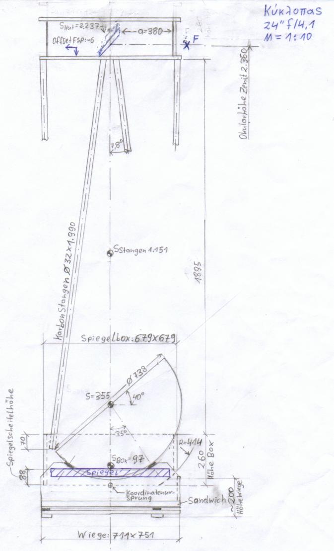
Mirror Box: It is made of 12 mm (0.47") Baltic Birch plywood at a total height of 260 mm (10.2") only. I transported the wood on my bicycle and couldn't believe, that this tiny sheets in my backpack should become the core piece of a 24-inch. The trick is, to place as large as possible triangular reinforcement braces into the corners, this is what really adds enormous stability to the structure. At the rear side I followed Martin Birkmaier's idea and implemented carrying handles made of 25 (1") al-pipe into the reinforcement corners. Thank you Martin for this genius tip! With an additional carrying belt trough the handles I can lug the fully equipped 37 kg (81.6 pounds) box on my shoulder in an upright position trough doors and narrow gangways. How heavy something appears, depends on how good you can grip it and how near the mass is at your body. Elegant ladies carry their make up mirror in the vanity bag on their shoulder too! |
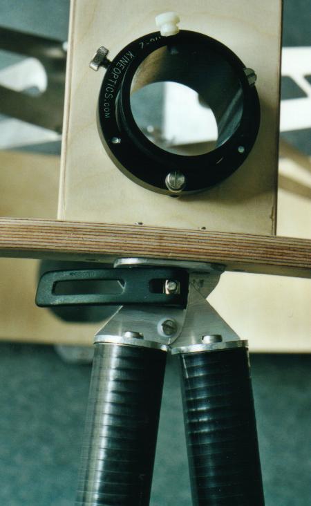 |
Trusses: A classical "Truss Tube Design", but with 8 carbon fiber trusses of 32 mm (1.25") diameter, 1 mm (0.04") thickness and 1.98 m (78") length. They are slightly oversized, since I couldn't get thinner ones in this length, but rock solid and ultra light. Carbon trusses have major advantages:
The single, but very serious draw back: they have cost 500 ($ 460), witch is more than 5 times as much as with aluminum. |
 |
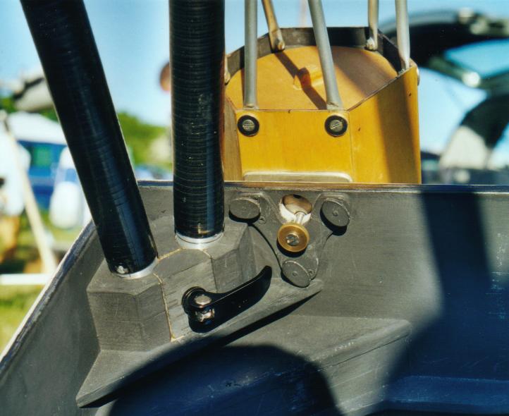
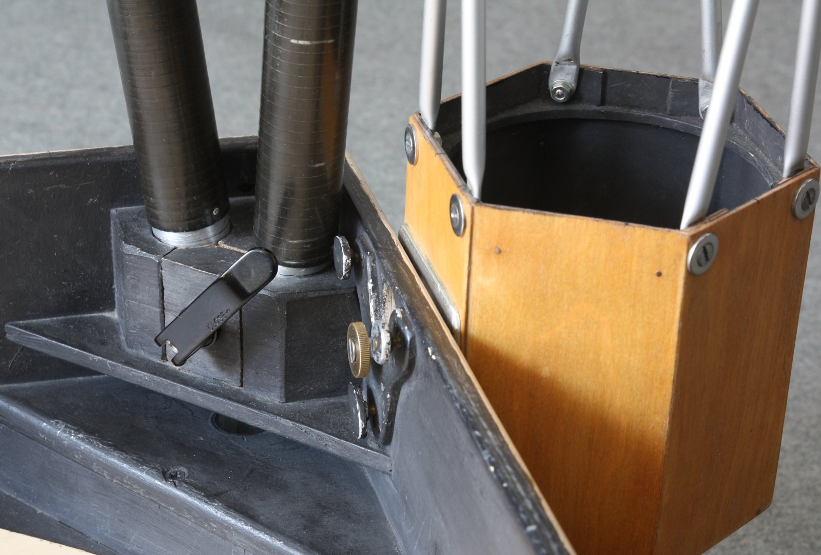
Upper pole seats: The trusses are connected in pairs with L- brackets of 3 mm (0.12") thickness via an M4 (0.16") joint with polyamide washers, to allow for angular movement. This method is structurally superior to individual trusses, since there is formed a closed force triangle, which does not transmit any additional momentum to the cage ring. The bores are slotted, to accept the M5 (0.2") bolt at the cage without removing any parts. They are tightened with quick fasteners like used at mountain bike saddles. You click 4 times and are done, instead of tightening and loosening 8 clamp knobs. |
|
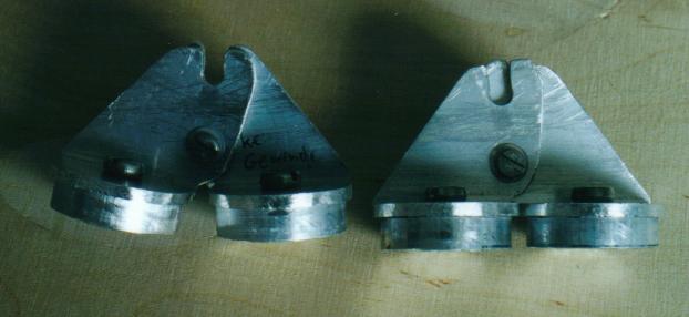
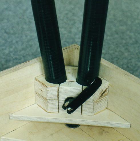
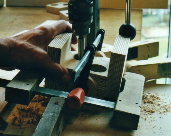
Lower Split Block Sockets: They are made out of wood, small and lightweight. The trusses are fastened in pairs with bicycle quick fasteners, so again 4 "clicks" instead of screwing up 8 times. On top of this they stabilize the mirror box in the corners, so exactly where the forces are transmitted to. However, the issue is, how to bore 32 mm holes in wood in an 8° angle to the side and an 1° angle outwards. I did not succeed with my simple drilling machine on a wobbly stand and so the trusses looked into various directions other than they should to, a big mess! How to bypass the tolerances? here is the trick: I glued small connecting pieces of 30 mm (1.2") aluminum pipe with epoxy into the carbon trusses which will go instead into the wooden sockets. Then I warped one layer of thin tape around this studs, set up the whole telescope, aligned it properly and fixed it in this position against the wall. Now I poured epoxy with an injection syringe into the remaining gap between 30mm aluminum stud and 32 mm bore. After the epoxy was set, I pulled out the trusses and split the blocks. Result: All trusses fit nicely into the new epoxy inserts of the wood blocks and are exactly aligned! |
|
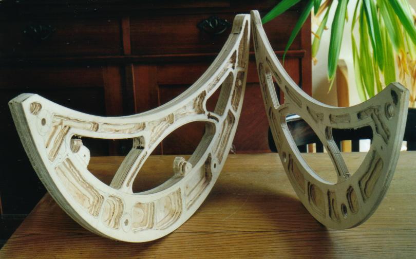
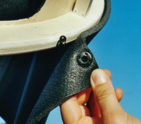
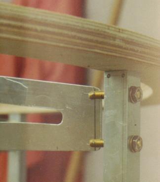
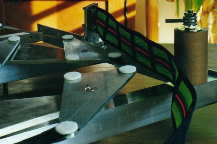
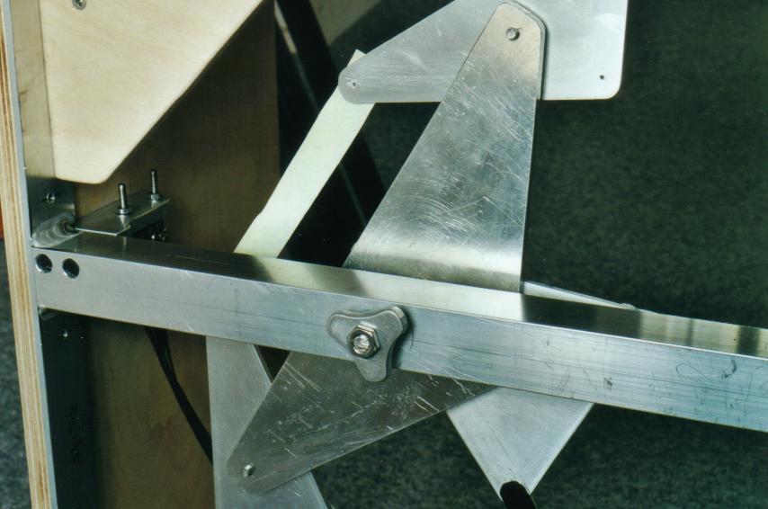
Altitude Bearings: Bernd Schatzmann's crescent Moon bearings not only look pretty, they are lightweight and stable too. Mine are 740 mm (29") diameter, 36 mm (1.4") thickness. They consist of two half sections each, which are routed out at the inner sides to save weight. So they weigh both together 3.8 kg (8.4 lb) including bolts. They are fastened with M8 levers and T-nuts at the mirror box. For transport and storage they can be removed and fit into the mirror box. Only with removable "ears" you have a chance, to fit a 24" telescope into a small car. |
|
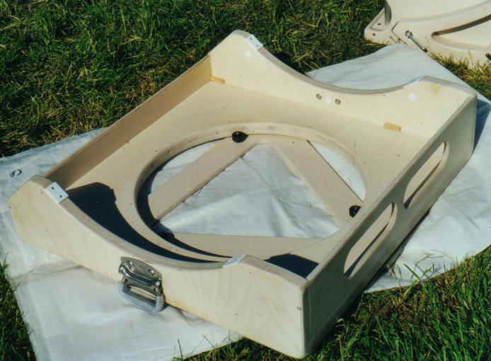
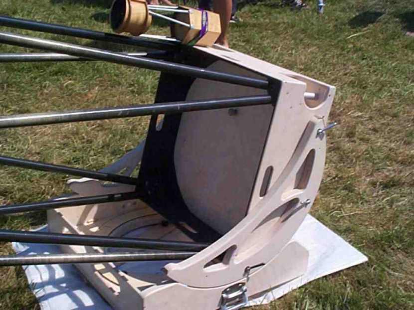
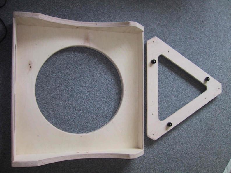
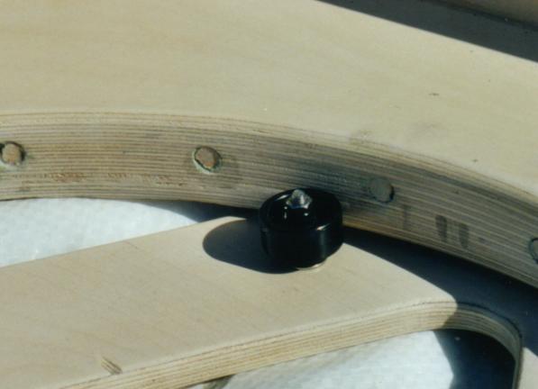
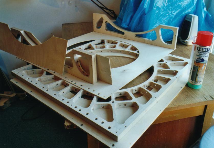
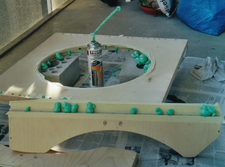
Rocker Box: Inspired by Greg Babcock's 24" I chose an open middle / no center pivot structure through which the mirror and collimation bolts can swing. This saves another 3-4 cm (1.2-1.6") height, the mirror floats in 45° position a mere 6 cm (2.4") above the grass! The triangular ground board is made of 12 mm (0.47") plywood. 3 small side wheels instead of a central hub pivot the rocker onto the ground board. The bottom is made out of a 24 mm (0.94") thick cutout plywood, which is sandwiched between a 6.5 mm (0.25") and 3 mm (0.12") sheet. The side panels are a 3 / 24 / 3 mm (0.12" / 0.94" / 0.12") sandwich construction too. The voids are filled with 2 component insulation foam. This method proved extremely stiff and lightweight. The total weight of the fully equipped rocker is 9.5 kg (20.9 lbs) and is 20 cm (8") high.
|
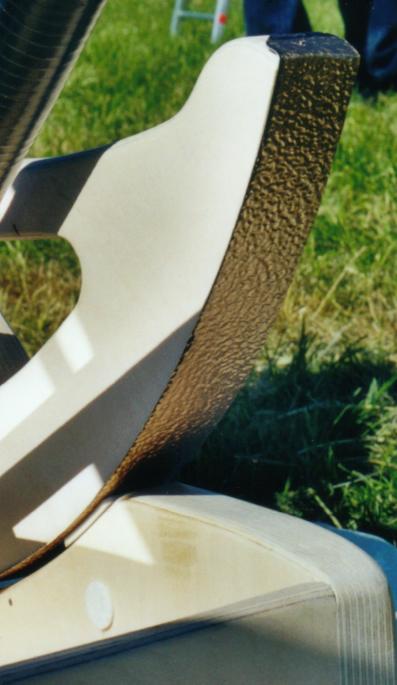 |
Bearing Material: Besides the mirror quality the most important part of a Dobsonian! As a contact partner to the teflon pads I chose pebbled "gold anodized" aluminum sheet, like used to cover window benches. Due to the pretty hard coating and the rough textured structure it has a similar performance like "Ebony Star" and is superior to the normal fine textured laminates for kitchen counter tops that can be found in Europe. It enables smooth tracking without sticking. For the azimuth I love Glasbord from the USA, which is in my opinion the best you can do to your teflon. In Europe you can get it at hydewa. |
|
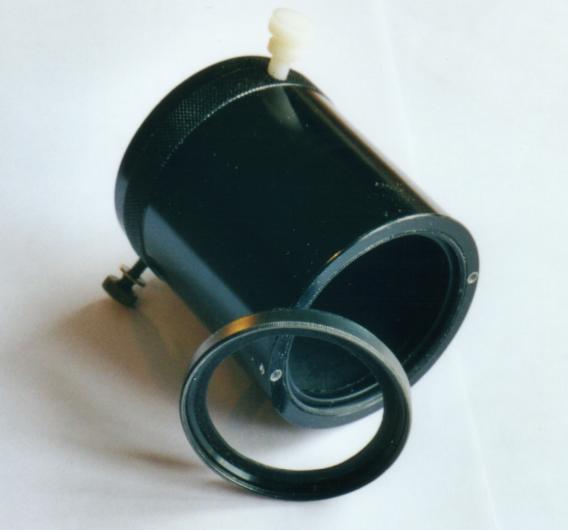
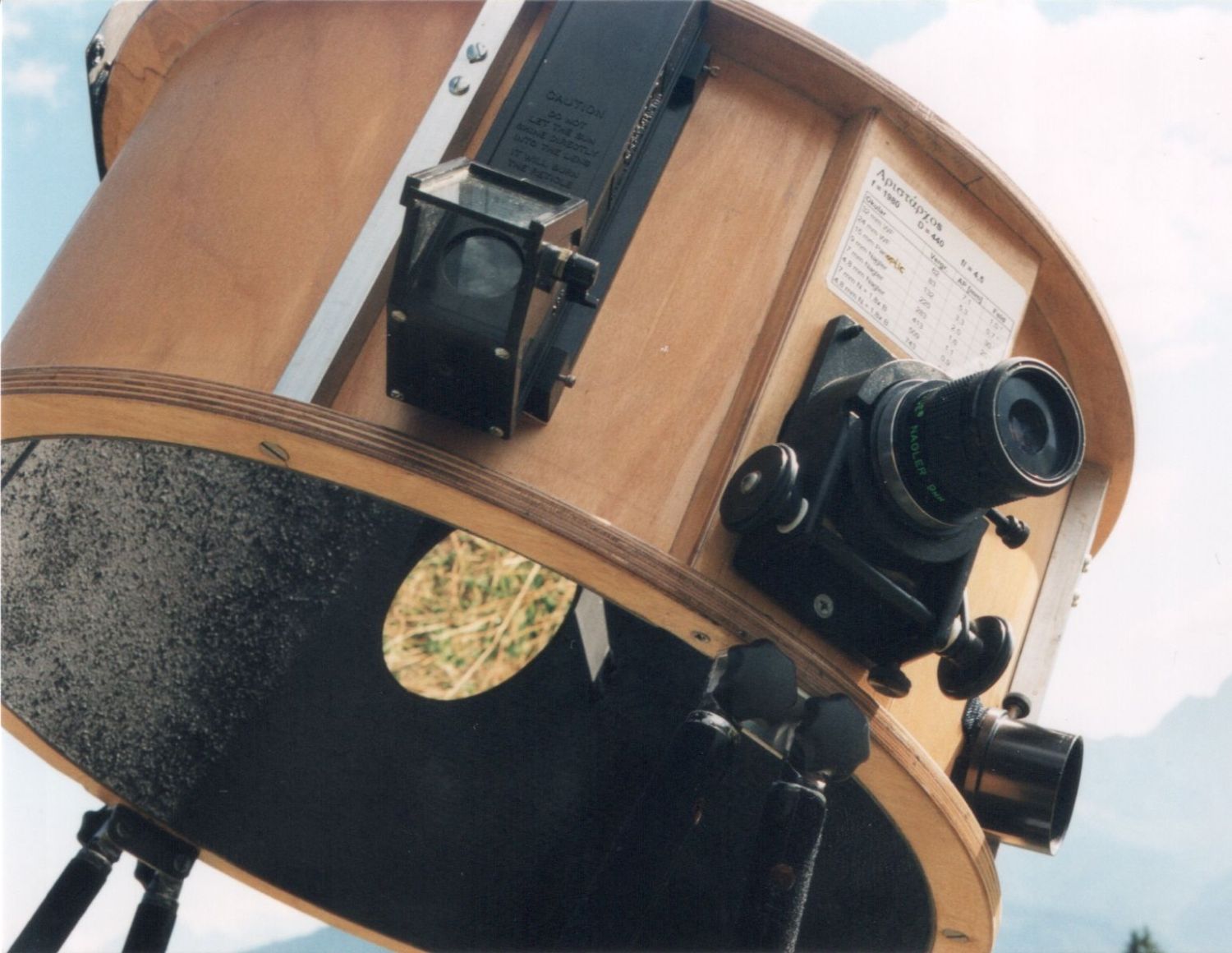
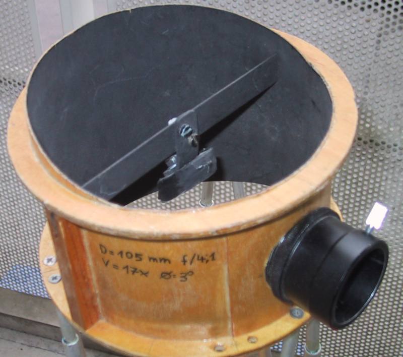
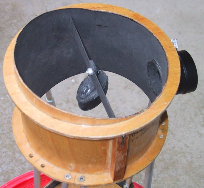
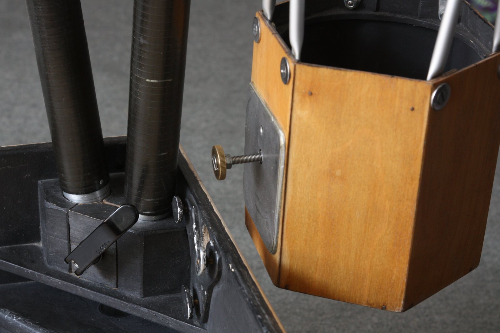
The 4" f/4 Newtonian Finder It weights 1 kg (2.2 lb) only and is placed adjustable near the balance point of the telescope. Collimation is done within seconds via a center pull bolt and 3 push bolts. Secondrary holder details see at picture from the front and picture from the back. I hate finders with star diagonals and their confusing mirror views. This one here shows the same orientation than the main instrument and keeps your mind free from "translating" back and forth reversed views. In combination with the Quick Finder this thing finds everything, that can be found. I use it also quite often as as rich field telescope, or guide other people at star parties, who are not so experienced in driving a Dobsonian. The mirror is self made, of course. The finder is fixed at the mirrorbox via a M5 knob, that is inserted into a keyhole mount. There collimatiting knobs press against the Al-plate of the finder. See picture 1, picture 2 and picture3. Other examples see Newtonian Finder (German text) |
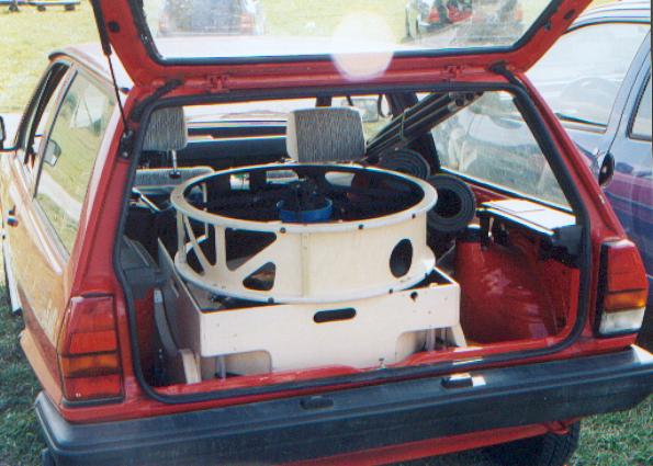 |
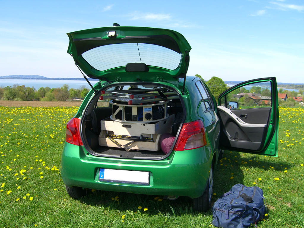
Transport: 24 inches in a small Volkswagen Polo or in a Toyota Yaris |
^ To top of this page
To mirror making
Home | Imprint | Privacy Policy | about |